
Analysis of Core Functions of OTC Daihen Robot Arc I/F Board (Interface Board)
When establishing a fully automated arc welding workstation, high-speed, high-fidelity electrical communication must be maintained between the robot control cabinet, the external digital welding power source (such as OTC’s classic DM350, WB-M500, WB-P500 series, etc.), and the external tooling fixture system. The OTC DAIHEN Arc I/F Board (Arc Interface Board) is the core hardware designed exactly for this purpose. A robot control cabinet system typically allows the additional installation of one such expansion board.
This board not only integrates a dedicated serial bus port directly connected to the arc welding control device but also opens up a fully functional general-purpose I/O switching terminal block to users. This terminal block provides hardware-level 8 digital inputs (Inputs) and 8 digital outputs (Outputs). By standardly connecting these I/O wires, the master control system (such as the fieldbus PLC or external tooling safety interlock circuit) can transmit or capture critical logic in real time, such as arc ignition success signals, wire break detection, protective gas flow anomalies, and fatal system errors. This serves as the foundational wall guaranteeing the safe and efficient operation of the automated arc welding line.
Official Ordering and Maintenance Instructions: If you purchased the OTC welding robot system as a complete set with the original arc welding control device (complete welding machine) during your purchase, this Arc I/F Board is usually pre-installed on the main motherboard or specific card slot inside the control cabinet at the factory, requiring no secondary installation by you. If this board was purchased separately later on to upgrade the production line, add external axes, or replace a discontinued old model, please strictly follow the industrial standard safety steps below to execute the hardware quick replacement and harness hardwiring.
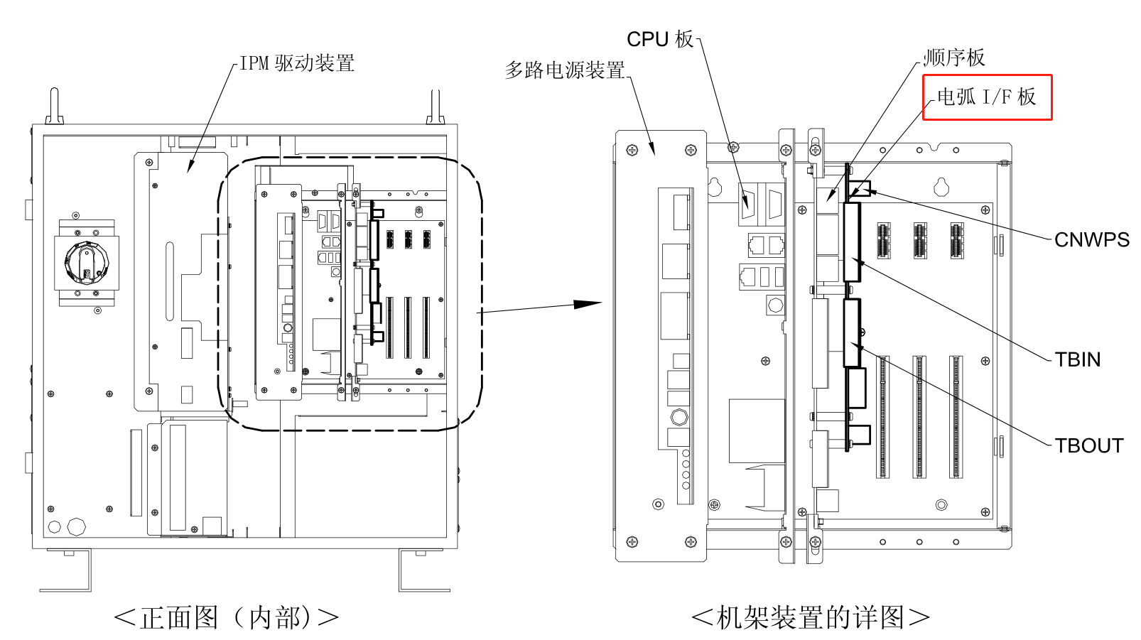
Figure 1: Official Standard Installation Location Diagram of OTC Daihen Welding Robot Arc I/F Board Inside the Cabinet
II. Five-Step Tutorial for Standard Installation and Hardwiring of Arc I/F Board (Interface Board)
Before adding electrical hardware inside the cabinet, you must ensure that the power environment of the entire machine is in an absolutely disconnected and safe state:
Cut Off Main Distribution Grid Power, Open Circuit Breaker, and Let Capacitors Discharge
⚠️ Electrical Anti-Shock High-Risk Interlock Standard: Before starting, please thoroughly pull the switch to disconnect the feed switch of the workshop’s main distribution power grid. Disconnect the main air circuit breaker on the control cabinet panel. Because there are large-capacity electrolytic filter capacitors inside the control cabinet inverter room, you must force a wait time of at least 5 minutes or more until the residual high voltage is completely discharged through the braking bleeder resistor before opening the cabinet to operate. Operators must wear anti-static ESD wristbands to prevent human static electricity from breaking down the microprocessor chips on the board.
Remove External Structure Panel of Control Device and Plan Operation Space
Use a Phillips screwdriver to remove the dust-proof sealing metal protection panel on the right side or rear back of the OTC robot control cabinet. Centralize and store the screws. Clean the metal dust around the box to prevent suspended conductive metal iron powder from falling onto the CPU board or servo amplifier power transistors inside the cabinet when the panel is removed, ensuring a highly clean internal electrical environment.
Process Holes on the Protective Sealing Panel and Thread External Signal Cables Through
According to the bundle diameter size of the external general-purpose I/O control harness of the arc interface board, perform mechanical drilling or punching on the removed side panel or the dedicated cable outlet hole plate. After drilling, an original matching insulated protective rubber grommet (flange sheath) must be added to the edge of the metal hole. Subsequently, thread the double-shielded multi-core I/O signal cable vertically through it to eliminate abnormal cutting and open-circuiting of the harness by the metal panel caused by severe inertial vibrations during operation.
Accurately Insert the Arc I/F Board into the Mother Slot and Execute Metal Fastening
Referencing the guide in Figure 1, vertically align the newly purchased original Arc I/F Interface Board with the dedicated bus slot on the main baseboard of the cabinet, press the edges with both hands, and slide it in smoothly. After confirming that the gold finger area is tightly engaged with the mother slot, tighten the physical metal fastening screws around it (with moderate torque) to eliminate impedance drift caused by vibration. Subsequently, organize the multi-core external shielded control harness threaded through, and firmly screw the panel back onto the outer wall of the control device.
Execute Standard Terminal Wiring of General 8-In/8-Out I/O Wires
Use a micro flathead screwdriver to connect the multi-core copper leads of the external cable, after wire stripping, one by one into the general I/O terminal block array integrated on the Arc I/F Board. When wiring, the stripping length should be strictly controlled to about 6mm to ensure that the copper wire is completely retracted into the wiring hole with no burrs exposed. Fasten the wiring terminals with torque to prevent loosening. Please fully cross-reference the standard signal mapping definition matrix below for wiring.
Classic Signal Definition Matrix for OTC Robot Arc I/F Board General I/O Terminal Block
When executing Step 5, equipment integrators and external PLC debugging engineers are requested to strictly cross-reference the following table for switching logic interlocking. This grid table uses a deepened solid line design, clear and rigorous:
| Signal Classification | Signal Pin (Nominal) | System Default Standard Function Definition | On-Site Typical External Devices and Interconnection Roles |
|---|---|---|---|
| Digital Input (8-Channel Inputs) | IN1 ~ IN2 | Welding process external start/close self-lock permission | Connect to central PLC for robot welding hard interlock signal permission. |
| IN3 | Shielding gas flow status check detection (GAS CHECK) | Connect to the low-pressure switch contact of the flow sensor of the gas line high-pressure reducing valve. | |
| IN4 ~ IN5 | External tooling positioning pin fully home ready feedback | External connection to the pneumatic travel limit switch of the workstation positioner tooling fixture. | |
| IN6 ~ IN8 | System custom quick jump/program interrupt number | Connect to master console buttons for manual site intervention or torch cleaning pause. | |
| Digital Output (8-Channel Outputs) | OUT1 (WELDING) | Robot welding execution in-progress output (Passive/Active) | External connection to console red indicator light or master PLC, warning of high arc voltage danger. |
| OUT2 (ARC_EST) | Arc ignition successful detection feedback | Notifies positioner axis to start rotating, executing synchronous linked welding. | |
| OUT3 (WIRE_ERR) | Welding torch front-end wire sticking/breaking anomaly alarm | Outputs to alarm buzzer, prompting on-site operators to troubleshoot wire feeding faults. | |
| OUT4 ~ OUT8 | Tooling release command/special machine action linkage output | Externally connects to mid-mounted solenoid valve power device, controlling process gas valves and pneumatic clamps. |
Core Frontline Error Prevention Standards for Arc I/F Interface Board Hardware Installation and I/O Commissioning:
- Strictly prohibit connecting heavy-load strong power exceeding rated values to the external I/O side: The transistor optocoupler isolated input/output terminals onboard this general terminal block only possess amplitude-limited DC low-voltage carrying capacity. **Directly leading them out to drive external high-power AC solenoid valves or high-voltage contactor coils is strictly prohibited**. If controlling strong electrical equipment on-site is mandatory, a primary standard AC or DC isolated intermediate power relay (such as the common
4341-305relay or 24V power relay group) must be added to the outer side of the output pins of the Arc I/F board to prevent transient reverse ultra-high peak electromotive force from breaking down and burning the weak electrical chips on the arc board. - Cold boot refresh for communication fault codes: For some higher version control cabinet systems, after the initial installation of this expansion arc interface board is completed, before a system cold initialization is performed, the main CPU baseboard may still throw errors such as bus card unavailable or communication breakdown. If this occurs, after completing the wiring in Step 5 and verifying it is correct, please **completely turn off the main air circuit breaker power supply outside the control cabinet**, wait 15 seconds until the indicator lights in the cabinet are completely extinguished, and then re-close the switch to initiate a cold start. This forces the underlying Linux system to re-scan the PCIE/ISA bus slots, achieving automatic board registration and effective configuration.
️ Fast Access to Robot Bus Communication Boards and Official Professional Technical Support
Due to high-frequency arc radiation crosstalk, fluid cooling system leakage, or short-circuit strong power reverse in external I/O logic wiring in the workshop, it is highly likely to cause coking of the optocoupler chip on the Arc I/F interface board inside the cabinet, large-scale fluctuations in the multi-channel regulated switching power supply, or control cabinet main motherboard burnout. You are welcome to provide the exact parts material codes needed, directly contact us to obtain the latest official standard factory quotes, today’s real-time spot inventory, and advanced system integration solutions:
Why Strictly Stick to Genuine Imported OTC DAIHEN Electrical Components on Continuous Automated Welding Lines?
Fully automated multi-station arc welding workstations belong to typical automated heavy equipment with high-power frequency conversion inversion and high-quality signal interpolation in a high-frequency closed loop. The use of alternative boards or aftermarket unshielded communication lines from non-official regular channels makes them extremely susceptible to massive bus packet loss and freezing logic errors due to failure in meeting high-frequency ionizing radiation interference resistance standards at the moment of welder high-current activation, and even causing instantaneous electrical surges to break down the fragile core CPU card inside the cabinet. We solemnly promise that all full-digital arc interface baseboards, general multi-channel I/O signal processing boards, highly flexible shielded body follow cable harnesses, large-capacity retaining batteries, and handheld teach pendants sold are 100% brand new, genuine products imported from official channels. If you need to confirm today’s real-time spot inventory of spare parts, obtain full control cabinet TBEX external terminal block safety interlock loop wiring guides, or Fronius / Binzel and other special system accessories information, please feel free to consult our technical service team at any time.