
Core Functions and Quick Replacement Background of OTC Daihen Robot Control Cabinet IPM Drive Unit
In the OTC DAIHEN arc welding control systems (such as the common AX, FD11, FD19 series control cabinets), the IPM (Intelligent Power Module) Drive Unit is the current control hub responsible for driving the six-axis joint servo motors for high-dynamic feed. This unit directly bears the high-voltage rectification transmission of the DC main bus (DC 300V+) and three-phase frequency conversion inverter output.
During long-term high-load arc welding, frequent acceleration, deceleration, braking, or continuous operation in environments with overly dense workshop dust (leading to duct blockages and inverter heat accumulation), power transistor modules often suffer from electronic fatigue aging, or trigger circuit burnouts due to external electrical surges, leading to inverter-side short-circuit overcurrent alarms. Once a module breakdown is confirmed, a complete component quick replacement must be executed. Since there is residual high-voltage DC capacitor charge inside the control cabinet, the replacement must strictly follow these standard safety disassembly and assembly processes:
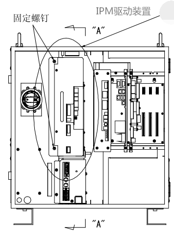
Figure 1: Exterior of Core OTC Daihen Robot IPM Drive Unit Component
Execute High-Voltage Power-Off, Anti-Static Protection, and Complete Capacitor Discharge
⚠️ Core Electric Shock Prevention Standard: Before starting, you must turn off the main distribution power grid circuit breaker and close the external circuit breaker switch of the robot control cabinet. After completely powering off the control cabinet, you must force it to stand and wait for at least 5 to 10 minutes. Use a multimeter’s DC high-voltage setting to measure the high-voltage DC bus (between P+ and N-), confirming that the residual voltage drops to safe levels (below 36V) before starting work. Operators must wear anti-static ESD wristbands before touching the boards to prevent static breakdown of microprocessors.
Remove Front Panel Control Cable Connectors and Metal Fastening Screws
Carefully unplug all ribbon cables and low-voltage control connectors connected to the front panel side of the IPM drive unit. When pulling out, pinch the plug lock catch and apply horizontal outward force; do not forcefully pull the wires. After all aviation plugs on the front panel have been removed, use a standard Phillips screwdriver to remove the two metal fastening screws located at the top and bottom of the unit, and safely store the screws.
Table 1: IPM Drive Unit [Front Panel Side] Connectors and Target Control Board Reference
| Connector ID (Pin) | Target Board Location and Signal Function Description (Target Location) |
|---|---|
| CNCOM | Connects to Main CPU Board (High-Speed Interpolation and Current Loop Data Bus) |
| CNSV | Connects to Sequence Control Baseboard (PLC Timing Interlock Control Main Signal Line) |
| CNVP | Connects to System Multi-Channel Switching Power Supply Unit (DC Low-Voltage Regulated Power Input) |
| CNMS, CNRST | Connects to Main Input Strong Power High-Voltage Contact Power Supply Control Main Power Device |
| (CN78E) | Connects to External Axis Expansion Control Cable 3 (Applicable only in 7-axis or models with travel rails) |
| CNFAN | Directly connected to the forced-cooling long-life axial cooling fan dedicated for the radiator below the module |
| CNR | Connects to High-Power Regenerative Energy Braking Bleeder Resistor Unit at the top of the control cabinet |
Slide Out Horizontally Along Rails for 200mm and Remove Right Inner Connectors
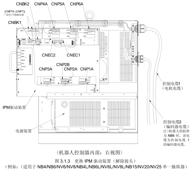
Grip the sheet metal reinforcing edge of the IPM unit panel firmly with both hands, slowly slide it outward horizontally along the built-in slot rail of the control cabinet by about 200 millimeters (never fully pull it out in one go directly). Once the device is pulled out 200mm, exposing the internal hidden wiring harness in the right side space, reach inward and disconnect all side connectors connecting the motor encoder and power dynamic lines one by one (refer to Table 2 for specific connector allocations).
Figure 2: Slide the Old IPM Drive Unit Smoothly Along Rails for 200mm to Reserve Clearance for Unplugging Right-Side Connectors
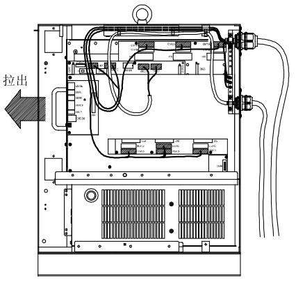
Table 2: IPM Drive Unit [Right Side Inner] Control Cable Connectors and Applicable Arc Welding Models Breakdown
| Connector ID (Pin) | Corresponding Multi-Core Shielded Cable (Cable) | Typical Applicable Welding Robot Models (Robot Models) |
|---|---|---|
| CNP1A ~ CNP6A | Machine Body External Control Cable 1 | Standard Payload Arc Welding Workstation Models: NB4 / NV6 / NB4L / NV6L / NB15 / NV20 / NH5 / NS3 and other Six-Axis Precision Welding Manipulators |
| CNP2B (Except NH5/NS3) | Multi-Axis Servo Power Cable 1 | |
| CNBK1, CNBK2 | Mechanical Brake Strong Power Cable 1 | |
| CNEC1, CNEC2 | Absolute Encoder Serial Signal Cable 3 | |
| CNP1B ~ CNP6B | External Axis Expansion Cable 2 | Additional Positioner/Gantry Axis Models: 1-Axis to 2-Axis External Tooling Axis and Gantry Hoisting Large Systems |
Figure 3: Internal Bus and Servo Drive Slot Layout Diagram of OTC Daihen Robot Control Cabinet
Slide Out Completely and Steadiy Lift to Remove Damaged Old IPM Drive Unit
After rigorously checking that all motor power plugs, brake circuit plugs, and feedback data lines inside the right side are completely disconnected without any wiring harnesses catching, apply steady force with both hands to slide the damaged old IPM drive unit completely out of the front of the controller along the side rail guides. When removing, be careful to lift the bottom with both hands to avoid impacting the large electrolytic filtering capacitors on the bottom surface and the dense rear aluminum cooling fins, preventing structural fall injuries.
Push In New IPM Drive Unit and Lock Internal Side Wiring Harnesses
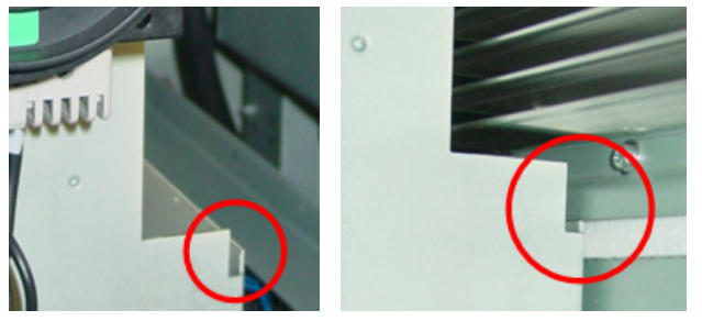
On the contact surface of the rear aluminum cooling fins of the new original IPM drive unit ready for replacement, apply a thin, even layer of dedicated industrial-grade high-thermal-conductivity silicone grease (thermal paste) to ensure the module seamlessly mates with the cabinet’s sheet metal thermal backplate without any air insulating layers. Subsequently, align the new device with the guide rails and slowly push it in from the front by about 200 millimeters. Within this hovering gap, realign and insert all power cables, brake lines, and absolute feedback plugs on the right side corresponding to Table 2. You must hear a “click” locking sound, and lightly pull the harness to verify it is absolutely secure.
Figure 4: Push the Brand New Genuine Imported IPM Drive Unit Into the Guide Slot and Align with the Front Panel Horizontal Plane
Fully Push the Power Drive Component In and Execute Mechanical Fastening
After confirming the side hidden connectors are securely locked, apply steady force to push the new IPM drive unit assembly completely to the bottom until its front outer metal panel is completely flush with the front horizontal frame of the cabinet. Re-screw the two metal fastening screws removed in Step 2 into the top and bottom screw holes. Use a torque wrench to alternately tighten them symmetrically; the force should be moderate, and cross-threading is strictly prohibited to prevent heat conduction efficiency deterioration due to uneven stress contact on the cooling fins.
Re-connect Front Panel Plugs According to Connector Matrix Full Restoration
Cross-referencing the Table 1 data in Step 2, connect back all multi-core ribbon cable plugs sequentially hanging on the front side of the control cabinet, including CNCOM, CNSV, CNVP, CNMS, as well as CNFAN for the cooling fan and CNR for the regenerative resistor. You must ensure that the lock catches and metal self-locking shells of each aviation plug are pushed completely to the bottom, eliminating any looseness risks, preventing wire feed speed jitter or communication disconnect errors caused by excessive contact impedance.
Final Multi-Link Point Check Closing, Cold Start Boot Testing
Before closing the power, execute final multi-link closed-loop blind spot troubleshooting: confirm there are no leftover conductive metal hardware items such as screwdrivers or washers inside the control cabinet, and inspect the peripheral branch lines of the cabinet for abnormal scrapes. After confirming everything is intact, close the main air circuit breaker switch, connect the main power grid, and cold-start the robot control system. Observe the drive indicator light status on the teach pendant loading interface. If the self-test passes without fault codes popping up, click to restore operation preparation. The complete set of quick-replacement procedures is officially successful.
⚠️ Core Troubleshooting and Board Burn-Prevention Standards for Servo Power Inverter Drive Unit Replacement on Site:
- Blind forceful replacement without verifying codes is strictly prohibited: Even under the same series of control cabinets (e.g., within a control cabinet), robots with different tonnage and mechanical axis stiffness configurations feature fully unique matching IPM servo drive units (such as main board circuit codes
L23430A00,L21730A00,L8310S00, etc.) regarding their programmed bottom-layer gate opening and closing pulse characteristics and power ratings. Before ordering and inserting a new spare part, you must strictly compare the nominal models on the original nameplate word by word. Blindly forcing a replacement with imitation parts or substitutes makes it highly susceptible to impedance mismatch at the moment of high-current arc ignition, directly leading to large-scale secondary burnout of the brand-new drive unit and main CPU board. - Emergency handling for zero-position loss alarms after replacement: After the absolute encoder cables have been completely disconnected and powered off for several minutes, the motor’s multi-turn absolute value counting chips often experience origin deviation due to residual capacitor discharge. It is extremely easy for origin data loss faults similar to battery undervoltage to pop up during rebooting. If this occurs, do not panic and blindly disassemble the motor. You only need to refer to our dedicated technical guide, enter expert mode privileges via the teach pendant, and execute the **standard absolute encoder origin reset and five-point zero position correction procedure**, which can instantly restore the workstation’s geometric interpolation trajectory accuracy of ±0.05mm.
️ Quickly Acquire Robot Control Cabinet Core Power Components and Authorized Technical Support
Workshop automatic arc welding lines face typical industrial conditions like continuous high loads, high heat, and high electromagnetic interference. Once an IPM drive module breaks down, it is often accompanied by burnouts in regenerative bleeder resistors, multi-channel switching power supply fluctuations, or sequence board logic damage in the control cabinet. You are welcome to provide the exact part material codes you need and contact us directly to obtain the official standard factory quotes and real-time spot inventory of the latest original genuine imported IPM inverter drive devices (L23430A00 / L21730A00), high-breaking air circuit breakers, large-capacity retention batteries, and complete body cable assemblies:
Why Strictly Stick to Genuine Imported OTC DAIHEN Electrical Components on Heavy-Duty Automated Arc Welding Lines?
Fully automated multi-station digital arc welding systems are precision heavy industrial equipment characterized by high-power electrical inversion calculations with high closure loops. The use of any non-original refurbished modules or low-end aftermarket servo power devices is highly likely to fail in meeting high-frequency ionizing radiation immunity standards. The moment the high-frequency high-voltage pulse of arc ignition triggers, electromagnetic harmonic crosstalk occurs, ultimately rendering the expensive main CPU calculation card inside the control cabinet completely scrapped, leading to massive line-wide paralysis and production stoppage. We solemnly promise that all full-digital six-axis integrated drive amplifiers, IPM intelligent power inverter modules, CPU control mainboards, and multi-layer high-shielded body main cable wires sold are 100% brand new, genuine imported products through official authorized channels. If you need to request the control cabinet fault code clearance breakdown, verify the servo power inverter room electrical wiring diagrams, or require Fronius special high-precision arc welding parts information, please feel free to inquire our technical service team at any time.